| Version 16 (modified by , 13 years ago) ( diff ) |
|---|
-
6. Case 2: Software Installation, Configuration and Operation
- 6.1 WiMAX OID and IP Address Assignment
- 6.2 Key Configuration Parameters
- 6.3 Base Station Server Installation
- 6.4 Setup NEC BTS
- 6.5 Configuration of ASN-GW Controller and WiMAX RF Agg Mgr
- 6.6 Configuration of CLICK
-
6.7 OMF/OML Installation
- 6.7.1 Installation and Test Instructions
- 6.7.2 Installation of the Aggregate Manager machine(VM)
- 6.7.3 Configuring the Aggregate Manager (AM)
- 6.7.4 Installing the Experiment Controller (EC)
- 6.7.5 Configuring XMPP
- 6.7.6 Preparing the Experiment Nodes
- 6.7.7 Using the testbed
- 6.7.8 Instrumenting your experiment
- 6.8 OMF/OML Configuration
-
6.9 Operations and Testing
- 6.9.1 Login to Base Station Server
- 6.9.2 Login to BTS
- 6.9.3 ASN GW Operation
- 6.9.4 RF Transmission
- 6.9.5 SAM Monitoring
- 6.9.6 CLICK Modular Router Monitoring
- 6.9.7 Mobile Station Registration
- 6.9.8 Traffic Monitoring
- 6.9.9 Login to OMF as Experimenter
- 6.9.10 Use of OMF to Configure Service
- 6.9.11 Use of OML to Monitor BTS
- 6.9.12 Use of OML to Monitor Service
6. Case 2: Software Installation, Configuration and Operation
Fig 2-2) Case 2 WiMAX Base Station Configuration

Fig 3-2) Case 2 Detailed WiMAX Base Station Configuration
Fig 4-2) Case 2 WiMAX Software Configuration
6.1 WiMAX OID and IP Address Assignment
| Campus | OID | IP Range |
| WINLAB | 44:51:DB:00:00:XX | 10.3.0.XX |
| NECLabs | 44:51:DB:00:01:XX | 10.3.1.XX |
| BBN | 44:51:DB:00:02:XX | 10.3.2.XX |
| Stanford | 44:51:DB:00:03:XX | 10.3.3.XX |
| Poly | 44:51:DB:00:04:XX | 10.3.4.XX |
| UMass | 44:51:DB:00:05:XX | 10.3.5.XX |
| Columbia | 44:51:DB:00:06:XX | 10.3.6.XX |
| UColorado | 44:51:DB:00:07:XX | 10.3.7.XX |
| UWisconsin | 44:51:DB:00:08:XX | 10.3.8.XX |
| UCLA | 44:51:DB:00:09:XX | 10.3.9.XX |
Each campus can have up to 127 basestations (each BS needs two addresses) and/or multiple ASN gateways. The basestations are assigned OIDs and IPs starting from 1 and counting up while ASN gateway machines are assigned IP addresses that are assigned starting from 254 and counting down. For example, first basestation in WINLAB gets IP address on primary controller of 10.3.0.1 and the IP address for the networking card of 10.3.0.2 while the gateway machine gets 10.3.0.254
Issue: Should all use BBN OID, since it is the only one offically regsitered? Also, that all MSs would use same OID?
6.2 Key Configuration Parameters
These are the key parameters, that are gathered and then held in the yaml configuration file
# NOTE: use only 'spaces' to indent !
# ('tab' indents are not supported by the ruby yaml parser used to read this file)
#
# This is the Config file for the WiMAXRF GridService
#
---
wimaxrf:

  asngw:
   if: eth1
   ip: 192.168.1.50
   port: 2231
   id: ASNGW000
   tecnh: 3
   dsc: IP-Config-Mgmt

  click:
    def_gw: 10.41.0.1
    net_mask: 255.255.0.0
    def_ip: 10.41.0.254

  bs:
   ip: 192.168.1.10
   mask: 255.255.255.0
   bsid: 00:00:04:00:00:01
   frequency: 2590000
6.3 Base Station Server Installation
6.3.1 Expected OS: Ubuntu 9.04
lsb_release -a
No LSB modules are available.
Distributor ID: Ubuntu
Description:    Ubuntu 9.04
Release:        9.04
Codename:       jaunty
6.3.2 Setup Ethernet Interfaces
It is expected that there be 3 wired Ethernet interfaces named: eth0, eth1, eth2. You may need to edit /etc/udev/rules.d/70-persistent-net.rules to make the names
reflect the correct physical ports. The /etc/network/interfaces file should look similar to this:
# This file describes the network interfaces available on your system
# and how to activate them. For more information, see interfaces(5).

# The loopback network interface
auto lo
iface lo inet loopback

# This interface connect to the Base Station

auto eth1
iface eth1 inet static
address 192.168.1.50
network 192.168.1.0
netmask 255.255.255.0
broadcast 192.168.1.255

#This is the gateway interface, it should get a routeable address from DHCP

auto eth2
iface eth2 inet dhcp

#Reserved for future USE

auto eth0
iface eth0 inet static
address 10.41.0.3
network 10.41.0.0
netmask 255.255.0.0
broadcast 10.41.255.255
6.3.3 Install Required Packages
- Configure apt/sources to include mytestbed.net and orbit-lab.org. Edit the /etc/apt/sources.list and add the following lines:
deb http://pkg.mytestbed.net/ubuntu karmic/
deb http://packages.orbit-lab.org/ubuntu jaunty main
- Update information based on the changed sources.list.
sudo apt-get update
- Now install the ASN-GW software
sudo apt-get install asn-gw0.9.0 click1.6.0 omf-wimaxrf-aggmgr-5.2
This will install 333MB or so worth of packages. You will need to confirm some of the packages from our repository.
Create Debian Package
Create Package Site
6.4 Setup NEC BTS
Please note: Do not restart BTS until all changes are complete. If you do happen to restart, you will have to use the serial interface to connect to the BTS.
6.4.1: Step 1 Configuring the IP
We'll need to adjust the ip's of both interfaces. They're managed via two independent files which exists on two different machines/ip combos.
- The "DSP" machine:
- Copy the attached networkenv.orbit file locally (to your console) and edit it's addresses to reflect
your organisations Address Structure. If this is the first BTS in your organization
your address should be of the form 10.3.X.1, where X is the numerical ID given to your group. You'll only need to edit the #MACO segment of information.
You will also need to set the NAMESERVER flag to something reasonable like googles public DNS (8.8.8.8), or a specfic DNS in your network. Note that we're using
class B addresses.
#MAC0
export INTERFACE_0=eth0
export IPADDR_0=10.3.Y.1
export NETMASK_0=255.255.0.0
export BROADCAST_0=10.3.255.255
export GATEWAY_0=10.3.YX.1
export NAMESERVER_0=8.8.8.8
- Copy the file to /flash/networkenv on the DSP machine (via SCP). The default IP of the DSP machine is 192.168.1.10.
scp networkenv.orbit root@192.168.1.10:/flash/networkenv
- Copy the attached networkenv.orbit file locally (to your console) and edit it's addresses to reflect
your organisations Address Structure. If this is the first BTS in your organization
your address should be of the form 10.3.X.1, where X is the numerical ID given to your group. You'll only need to edit the #MACO segment of information.
You will also need to set the NAMESERVER flag to something reasonable like googles public DNS (8.8.8.8), or a specfic DNS in your network. Note that we're using
class B addresses.
- The "Network" Machine
- Telnet to the N/W card at 192.168.1.42/24. User root as the username, you will not be asked for a password.
- Edit the /etc/network/interfaces eth1 entry to organisations Address Structure. It should be of the form 10.3.Y.2, for the first BTS. The entry should look
similar to:
auto eth1
iface eth1 inet static
address 10.3.Y.2
network 10.3.0.0
netmask 255.255.0.0
broadcast 10.3.255.255
gateway 10.3.Y.1
- Finally you'll need to configure your own interface to be in the same subnet as the BS Ip's. For the first BS it should be of the form 10.3.X.254.
6.4.2 Step 2 Configure the BTS software
- ssh to the new IP of the DSP machine.
ssh !root@10.3.Y.1
- Use wiset commands below to correct configuration on the BTS:
- Enter these Verbatim
wiset authgw_id 0x41534E47
wiset authgw_port 0x08B7
wiset asngw_id 0x41534E4757303030
wiset asngw_dp_port  0x08B7
wiset asngw_ep_port 0x08B7
wiset bs_rx_port 0x08B7
wiset frequency  2551500    or ??
wiset bs_tx_power 40
wiset bw_mode 0
wiset dlul_ratio 2
wiset ttg 296
wiset rtg 168
wiset framesync_mode 2
wiset antenna_gain 0
- These commands require you to change the IP paramter specfied in hex. The IP should that of the console's eth1 interface (which speaks to the BTS).
wiset authgw_ip 0x0A030047
wiset asngw_dp_ip 0x0A030047
wiset asngw_ep_ip 0x0A030047
- You will find your bsid (OID) on this page. Note remove the colons, and set the last two digits to
reflect the IP of the DSP machine (e.g. the first one should be 01).
wiset bsid 0x303030303030
- Enter these Verbatim
After this process, the BS will require a reboot.
This site converts dot quad to hex.
6.5 Configuration of ASN-GW Controller and WiMAX RF Agg Mgr
Configuration of software both for the ASN-GW and the WiMAX BTS is done through a single yaml configuration file on the ASN.
To enable the features we will need to copy the wimaxrf.yaml from /etc/omf-aggmgr-5.2/available to /etc/omf-aggmgr-5.2/enabled/.
Edit this file change settings (if needed)
# NOTE: use only 'spaces' to indent !
# ('tab' indents are not supported by the ruby yaml parser used to read this file)
#
# This is the Config file for the WiMAXRF GridService
#
---
wimaxrf:

  asngw:
   if: eth1
   ip: 192.168.1.50
   port: 2231
   id: ASNGW000
   tecnh: 3
   dsc: IP-Config-Mgmt

  click:
    def_gw: 10.41.0.1
    net_mask: 255.255.0.0
    def_ip: 10.41.0.254

  bs:
   ip: 192.168.1.10
   mask: 255.255.255.0
   bsid: 00:00:04:00:00:01
   frequency: 2590000
Making changes in this file should propagate changes to the ASN software and the BTS (IDU) software via the init script:
Usage of init script:
- init -wimax (verify)
- init -wimax -f (force)
- init -wimax -r (forces BTS parameters to default, except key parameters)
These are the files which are located in the /etc directory on the asn-gw machine.
In this section we will describe the changes required to the default configuration files for accommodating custom settings and IPs.
asnctrl
The points that need to be changed in the asnctrl.conf file are:
R6_BSID[0] = 00:00:04:00:00:00      // BSID allocated as per GENI
R6_BSAddress[0] = [10.3.Y.61]:2231  //IP address of the IDU
TunnelEndpoint = [10.3.Y.71]:0      //IP of the ASN - GW
asnctrl_ASNGW000
R4_BSID[0][0]=00:00:04:00:00:00
asnctrl_common
No changes are required in this file.
asnctrl_gre
This is an output file which shows the mapping of the client MAC address to the uplink and downlink GRE tunnel. This file does not need any configuration.
asnctrl_service_class
This file contains the mapping of the mac address to the service class. Sample entries are as shown below:
00:18:41:85:5e:a3       IP-Config-Mgmt
00:12:cf:b2:ad:9a       IP-Config-Mgmt
00:12:cf:b2:a4:e8       IP-Config-Mgmt
00:12:cf:b2:9c:73       IP-Config-Mgmt
00:1b:8b:54:02:9a       IP-Config-Mgmt
00:1b:8b:54:02:84       IP-Config-Mgmt
00:1d:e1:0a:5e:87       IP-Config-Mgmt
clasify-ctrl
This file is located here: /usr/share/asngw/classify-ctrl.sh IP addresses need to be updated here based on the settings used:
: ${DEV_R3:="eth0"}
: ${DEV_R6R4:="eth1"}
: ${MSADDR:="10.42.0.0/16"}
: ${R3_NETWORK:="10.41.0.0/16"}
: ${R3_ADDR:="10.41.0.3"}
: ${R6R4_NETWORK:="192.168.1.0/24"}
: ${R6R4_ADDR:="192.168.1.50"}
trapctrl
No changes are required in this file.
epctrl
R3LocalDevice = eth0
R4LocalDevice = eth1
R6LocalDevice = eth1
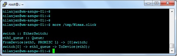
6.6 Configuration of CLICK
Configuration of the CLICK router is done by SAM.rb.
Here is an example configuration when no MSs are registered:
(sample)
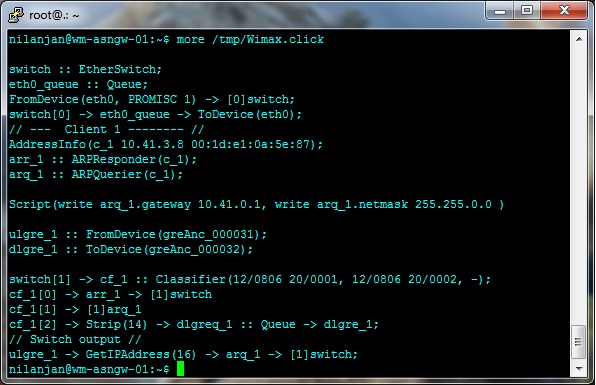
Here is an example configuration when one MS is registered:
(sample)
6.7 OMF/OML Installation
Procedure provided by Evan Zhang in Summer, 2010: This page contains all the information you need to understand the current OMF lab setting and how it was built.
Fig 7) OMF/OML System Configuration
References:
http://omf.mytestbed.net/wiki/omf/Installation_Guide_52
http://omf.mytestbed.net/wiki/omf/Ubuntu_Baseline
Lab setup:

6.7.1 Installation and Test Instructions
(You should always look at the reference instruction first,http://omf.mytestbed.net/wiki/omf/Installation_Guide_52)
Note: The OMF/OML 5.2 software(our current build target, 5.3 is on the way) mainly includes following packages(debian packages):
omf-aggmgr-5.2(Aggregate Manager) omf-expctl-5.2(Experiment Controller) omf-resctl-5.2(Resource Controller) oml-server oml-client openfire_3.6.4_all.deb(XMPP server).
omf-aggmgr-5.2, omf-expctl-5.2, oml-server, openfire_3.6.4_all.deb could either be built on the same machine or dedicated machine for each.
omf-resctl-5.2 and oml-client should be installed on each experiment node. We choose to build omf-aggmgr-5.2, omf-server, openfire_3.6.4_all.deb in one machine
(actually VM:herculaneum.gpolab.bbn.com) and omf-expctl-5.2 in another machine(actually VM: drasnia.gpolab.bbn.com).
For the internal test purpose, we made two kinds of the experiment node: VM nodes and physical nodes. VMs are used for the purpose of quick experiment test(without disk loading).
Physical nodes are used for testing disk image loading. For the network design, OMF requires that AM, EC and all the nodes are IP connected as control path. And between nodes
there should be experiment data path, either through wired, wifi, or wimax. For our current setting, two VM nodes are wired through eth1 as experiment data path. The physical
node 3 is a NC10 sumsung netbook which is a wimax enbaled node, so the data path suppose to be through our wimax station.
6.7.2 Installation of the Aggregate Manager machine(VM)
Network Setup
- Different from the reference instruction, we also have two interfaces eth0 and eth1 on AM machine. eth0 is control interface with internet accessibility and
eth1 is used to run our own DHCP server for the disk image loading purpose. Both eth0 and eth1 have fixed IPs and domain names assigned by GPOlab's infrastructure.
Configuring dnsmasq (DHCP, DNS and TFTP server)
- edit /etc/dnsmasq.conf and I add the following lines at the bottom of the file:
# Added by Evan for OMF installation
interface=eth1
dhcp-range=128.89.91.147,128.89.91.150,12h
dhcp-option=3,128.89.91.145
dhcp-option=121,128.89.91.30/32,128.89.91.146     <----- for dhcp assigned IP to ping 128.89.91.30, please refer to http://groups.geni.net/syseng/ticket/1004 for details
dhcp-option=option:ntp-server,128.89.91.30
dhcp-boot=net:control,pxelinux.0
enable-tftp
tftp-root=/tftpboot
- create a new file /etc/dnsmasq.d/testbed.conf and add your node DHCP details here:
dhcp-host=net:control,00:24:54:08:67:68,ini-wimax-dhcp-147,128.89.91.147
- /etc/init.d/dnsmasq restart
Set up PXE booting
- Follow the reference instruction and change the related IPs and MACs mentioned in the instruction to ours.
Inventory installation
- Follow the reference instruction and manually populate the inventory
One testbed info is added to table 'testbeds' with domain name 'sandbox1'
Three nodes info is added to the inventory (need to update four tables for each node: devices, motherboards, locations, nodes). They are,

node[1,1]: control IP: 128.89.91.31  (vm)
node[1,2]: control IP: 128.89.91.32  (vm)
node[1,3]: control IP: 128.89.91.147 (NC10 physical node)

For more detailed please go to: http://128.89.91.30/phpmyadmin, user:omf, pw:omf
6.7.3 Configuring the Aggregate Manager (AM)
- Follow the reference instruction and carefully change the IPs to ours.
- Test the CMC (Dummy) service with
 wget -qO- http://128.89.91.30:5052/cmc/allStatus?domain=sandbox1

<TESTBED_STATUS>
                <detail>
                        <node name='n_1_1' x='1' y='1' state='POWERON'/>
                        <node name='n_1_2' x='1' y='2' state='POWERON'/>
                        <node name='n_1_3' x='1' y='3' state='POWERON'/>
                </detail>
</TESTBED_STATUS>
6.7.4 Installing the Experiment Controller (EC)
- We can not find /etc/omf-expctl-5.2/nodehandler.yaml by following the reference instruction, we need to do,
sudo cp /usr/share/doc/omf-expctl-5.2/examples/nodehandler.yaml /etc/omf-expctl-5.2/nodehandler.yaml
- My nodehandler.yaml:
---
:econtroller:
  :config:
    :default:
      :domain: 'sandbox1'
      :repository:
        :path: ["../repository", "/usr/share/omf-expctl-5.2/repository"]

      :inventory:
        :url: 'http://128.89.91.30:5052/inventory'

      :web:
        :host: '129.89.91.31'

      :communicator:
        :type: 'xmpp'
        :xmpp:
          :server: '128.89.91.30'
          :password: 'gpo2010'

    :debug:
      :repository:
        :path: ['../repository']
      :communicator:
        :type: 'mock'
6.7.5 Configuring XMPP
Installing Openfire
'wget http://www.igniterealtime.org/downloadServlet?filename=openfire/openfire_3.6.4_all.deb' doesn't work, should be
wget -O openfire_3.6.4_all.deb http://www.igniterealtime.org/downloadServlet?filename=openfire/openfire_3.6.4_all.deb

username: admin, password: gpo2010
Creating the system nodes
omf_create_sysnode-5.2 128.89.91.30 128.89.91.31
omf_create_sysnode-5.2 128.89.91.30 128.89.91.32
omf_create_sysnode-5.2 128.89.91.30 128.89.91.147
6.7.6 Preparing the Experiment Nodes
- For VM experiment nodes (which is not mentioned in the reference instruction), the instruction is similar as preparing the baseline disk image. Reference: http://omf.mytestbed.net/wiki/omf/Ubuntu_Baseline
My nodeagent.yaml:

# This is an example configuration for the Resource Controller at NICTA
#
# NOTE: use only 'spaces' to indent !
# ('tab' indents are not supported by the ruby yaml parser used to read this file)
#
---
nodeagent:
  # Communication settings
  comm:

    # How many seconds can we go without a message from the node handler
    # before we assume we have lost connectivity and need to reset
    handler_timeout: 40

    # Number of consecutive handler timeouts before a 'handler lost'
    # will be declared.
    timeout_count: 2

    # Number of seconds to wait between consecutive RETRY requests
    retry_interval: 3

    # Number of seconds between consecutive HEARTBEAT messages
    heartbeat_interval: 10

    # Pause between resending previous messages
    resend_interval: 0.1

    server_port: 9026
    # local_if: Control Interface used with TCPServer Comm.
    local_if: eth0
    xmpp_server: 128.89.91.30
- For physical nodes (e.g. NC10 netbooks), we need to load disk image to it. How? We have two ways,
A. Run frisbee server and client manually:

1) Download the target disk image from Winlab. Gautam scped nc10-wimax.ndz to herculaneum.gpolab.bbn.com:/var/lib/omf-images-5.2/nc10-wimax.ndz
2) Boot NC10 into pxe image. Refer to 'Set up PXE booting' section of this document.
3) Run frisbee server at AM server(herculaneum): > frisbeed -p 7000 -i 128.89.91.146 -m 128.89.91.147 /var/lib/omf-images-5.2/nc10-wimax.ndz          <------Important: -i option must be specified here
4) Run frisbee client at NC10(a shell is offered by pxe image): > frisbee -p 7000 -i 128.89.91.147 -m 128.89.91.146 /dev/sda                          <------At both sides -m option IP could be replaced by a muticast IP e.g. 224.0.0.1
B. Load disk image through Experiment Controller

1) Same as A.1)
2) At Experiment Controller, run: > omf load "[1,3]" nc10-wimax.ndz
- After the nodes are up. The Resource Controller will report node's liveness to XMPP server on hourly basis. You can go to http://128.89.91.30:9090/user-summary.jsp (user:admin, pw:gpo2010) to check.
6.7.7 Using the testbed
At this point, you may want to run a test experiment. We choose to run a modified(get ride of the wireless configuration) hello world experiment with our two VM nodes. Based on this page http://omf.mytestbed.net/wiki/omf/Basic_Tutorials_for_Developing_Experiments, we developed our experiment description,
 # A) Define the 'source' group, which has the unique node [1,1]
 #     Nodes in this group will execute the application 'test:proto:udp_sender'
 #
 defGroup('source', [1,1]) {|node|

   node.prototype("test:proto:udp_sender", {
     'destinationHost' => '192.168.0.2',
     'localHost' => '192.168.0.1',
     'packetSize' => 256, # in Bytes
     'rate' => 8192 # in bits/sec

   })

   # mode can be 'adhoc' or 'managed' or 'master'
# Commented out by Evan for wired test
   #node.net.w0.mode = "master"
 }

 #
 # B)  Define the 'sink' group, which has the unique node [1,2]
 #     Nodes in this group will execute the application 'test:proto:udp_receiver'
 #
 defGroup('sink', [1,2]) {|node|

   node.prototype("test:proto:udp_receiver" , {
     'localHost' => '192.168.0.2'
   })

   # mode can be 'adhoc' or 'managed' or 'master'
# Commented out by Evan for wired test
   #node.net.w0.mode = "managed"
 }

 #
 # C)  Configure the wireless interfaces of All the Nodes involved in
 #     this experiment
 #

# Commented out by Evan for wired test
 #allGroups.net.w0 { |w|
 allGroups.net.e0 { |w|
   #w.type = 'g'
   #w.channel = "6"
   #w.essid = "helloworld"
   w.ip = "%192.168.0.%y" # the '%' triggers some substitutions
 }

 #
 # D)  When all the nodes are turned On and the all the applications
 #     are installed and ready, we can start to perform the experiment
 #
 whenAllInstalled() {|node|

   wait 30

   allGroups.startApplications
   wait 20

   Experiment.done
 }
You can run the experiment by doing:
> omf exec /path/to/hello_wire.rb
When I first ran hello_wired.rb experiment, I encountered a error at the resource controller side saying:
From /var/log/omf-resctl-5.2.log
2010-08-11 11:11:04 DEBUG nodeAgent::EthernetDevice: configure cmd: /sbin/ifconfig exp0 192.168.0.1 netmask 255.255.0.0
2010-08-11 11:11:04 ERROR nodeAgent::EthernetDevice: While configuring ip with 192.168.0.1 - CMD reply is: ''
Then I found out that in source file '/usr/share/omf-resctl-5.2/omf-resctl/omf_agent/agentCommands.rb', there is mapping between net.e0 ←→ exp0,
So I changed it to net.e0 ←→ eth1 in order for the experiment description to assign IP to eth1.
Now I can run our first experiment successfully.
6.7.8 Instrumenting your experiment
Basically, you need to insert some code into your application's source code to utilized the measurement library offered by OML.
Then the measurement data will automatically collected and sent to OML server during the runtime of your experiment.
For more detailed, please refer to: http://omf.mytestbed.net/wiki/omf/UsingOML
6.8 OMF/OML Configuration
6.9 Operations and Testing
6.9.1 Login to Base Station Server
Login through the console on the Base Station Server (ASN-GW) and test the following.
- The BTS should be reachable from the ASN-GW with the default IP setting:
- ping the BTS interface; it was assigned the fixed IP 192.168.1.10.
- measure the round trip times
- Power cycle the BTS through the use of stop and start scripts.
- Perform a hard reset if required (if updated parameter values are not reflected).
- There should also be a green light on the IDU after a software power cycle of the IDU.
- The software power cycle can be preformed by the following commands:
/etc/init.d/asn-gw stop
/etc/init.d/asn-gw start
- Ping the outside interface and see if the DMZ gateway is reachable from the ASN-GW
After successful completion we know that the ASN is able to send traffic both downlink to the IDU and outbound towards the internet.
6.9.2 Login to BTS
- To login:
(sample)
- Power cycle the BTS through the use of stop and start scripts.
- Perform a hard reset if required (if updated parameter values are not reflected).
- There should also be a green light on the IDU after a software power cycle of the IDU.
- The software power cycle can be preformed by the following commands:
/etc/init.d/asn-gw stop
/etc/init.d/asn-gw start
6.9.3 ASN GW Operation
To control the WiMAX base station, run the stop and start scripts as follows:
Start script:
/etc/init.d/snmpd start
/etc/rc.d/init.d/trapctrl start
sleep 1
/etc/rc.d/init.d/asnctrl start
sleep 1
/etc/rc.d/init.d/epctrl start
#sleep 1
Stop script:
/etc/rc.d/init.d/epctrl stop
/etc/rc.d/init.d/asnctrl stop
/etc/rc.d/init.d/trapctrl stop
/etc/init.d/snmpd stop
pkill -9 asnctrl
pkill -9 epctrl
A few simple checks to make sure things are working:
- There should be 3 running processes:
root      3128     1  0 19:10 ?        00:00:00 trapctrl
root      3137     1  0 19:10 ?        00:00:02 asnctrl
root      3227     1  0 19:10 ?        00:00:02 epctrl
- Some log files should start filling up in /var/log:
- asnctrl.log
- epctrl.log
6.9.4 RF Transmission
- Scan on the client and check if the basestation's signal is seen using the procedure described below. If we are able to connect step 2 can be ignored. Else try step 2.
Configure driver at the client to ensure all required parameters are configured correctly.
- Change the /etc/asnctrl_service_class.conf to include client and service class information.
- Possibly include SSID to match with the BTS
- Check center frequency to match with the BTS
- Enable (locks) if any
- Disable wifi if operating on a dual mode card (since quite a few times they work in a mutually exclusive mode)
- Enable a static IP setting at the client to allow for baseline IP connectivity
- If possible sweep the spectrum through an analyzer to determine proper transmission at the center frequency.
- Vary transmit power at the BTS using wiset calls on the BTS or through the web interface and then measure the corresponding changes on the analyzer.
6.9.5 SAM Monitoring
6.9.6 CLICK Modular Router Monitoring
6.9.7 Mobile Station Registration
6.9.8 Traffic Monitoring
Install wireshark on ethernet interfaces.
6.9.9 Login to OMF as Experimenter
6.9.10 Use of OMF to Configure Service
6.9.11 Use of OML to Monitor BTS
6.9.12 Use of OML to Monitor Service
Attachments (3)
- omf_gpolab_internal.png (148.2 KB ) - added by 13 years ago.
- WimaxClickNoMsRegistered.jpg (40.3 KB ) - added by 13 years ago.
- WimaxClickOneMsRegistered.jpg (85.8 KB ) - added by 13 years ago.
Download all attachments as: .zip