| Version 28 (modified by , 7 years ago) ( diff ) |
|---|
AirSynergy 2000
Table of Contents
Hardware Installation
AirSynergy Connections:

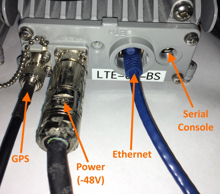
1. Networking Copper ethernet (1000BASE-T) 2. Power Connect power cable to -48 power supply with the provided cable 3. Serial Console (optional) If needed for debugging
Fully connected AirSynergy without weatherproofing covers should look like this:
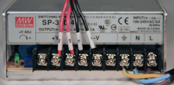
Power Supply
The AirSynergy supports direct connection to a -48VDC nominal power source.
Operating Voltage Range: -40.5 to 57 VDC
A power supply capable of 120W or greater is recommended (eg. Mean Well CLG-100-48).
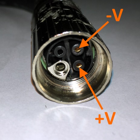
Power Supply Connector/Cable
TODO
The AirSynergy supports direct connection to a -48VDC nominal power source. Operating Voltage Range: -40.5 to 57 VDC
A power supply capable of 2A or greater is recommended (eg. Mean Well CLG-100-48).
Network Connectivity
Network connectivity is done via copper gigabit ethernet (1000BASE-T).
Serial Debug
The base station has a 9 pin connector (hidden behind a black hex bolt next to the port marked "ETH") which allows access to the serial console. This is useful for recovery purposes when the base station does not respond via software, SSH, or web interfaces. See Airspan LTE Base Station Serial Console for information on cable construction and serial port parameters.
Attachments (3)
- airsynergy_connections.jpg (150.3 KB ) - added by 7 years ago.
- airsynergy_power_cable.jpg (60.6 KB ) - added by 7 years ago.
- power_supply.png (322.1 KB ) - added by 7 years ago.
Download all attachments as: .zip